On-Board Diagnostics, or OBD, in an automotive context, is a generic term referring to a vehicle’s self-diagnostic and reporting capability. OBD systems give the vehicle owner or a repair technician access to state of health information for various vehicle sub-systems. The amount of diagnostic information available via OBD has varied widely since the introduction in the early 1980s of on-board vehicle computers, which made OBD possible.
Within the OBD II standard, there are several protocols for transferring data from the car to a diagnostic device.
| Name | Speed | Used by |
|---|---|---|
| ISO 9141 | 10 Kbits/second | most Asian and European manufacturers |
| J1850 PWM(Pulse Width Modulation) | 100 Kbits/second | Ford, Mazda |
| J1850 VPW(Variable Pulse Width) | 100 Kbits/second | primarily GM |
| CAN(Controller Area Network) | varies by application; see the Kvaser CAN page for more details | newer vehicles |
What can be pulled out from OBD-II?
- Real-time powertrain information (engine, speed)
- Real-time sensor data (temperatures, pressures, voltages)
- Running distance and time
- Vehicle Diagnostic Trouble Codes (DTCs)
- Vehicle identification number
What can be modified though OBD-II?
- Clear Vehicle Diagnostic Trouble Codes (DTCs)
- Manufacturer- or vehicle-specific ECU parameters
- Access and control other control units, such as air bag or ABS
Proprietary Sensor Readings
Though not part of the EPA’s OBD II standard, the diagnostic read-outs used by dealership technicians are also read through the OBD II connector. These service codes show you such things as:
- knock sensor operation
- FI pulse width
- ignition voltage
- individual cylinder misfires
- transmission shift points
- ABS brake condition
There can be over 300 readings available, depending on the vehicle manufacturer and model.
OBD-II and performance tuning
While the vast number of drivers want nothing more than dependable, economical transportation, many of us are looking to OBD-II for extra performance. Earlier on-board computer systems had chips that could be replaced to adjust engine parameters for extra speed and power. While the OBD-II systems are sealed and do not allow chip replacement, they do provide a real time data acquisition system that is useful to tuners.
Power loaders can actually reprogram the performance parameters of the OBD-II system to accommodate performance options. At the current time the number of models they can service is limited, but the range is being extended. Be sure the person doing your reprogramming keeps the car in compliance with EPA emission standards. As aftermarket manufacturers develop additional solutions, we will add their information to our links.
The CAN Bus
The CAN bus is a broadcast type of bus. This means that all nodes can “hear” all transmissions. There is no way to send a message to just a specific node; all nodes will invariably pick up all traffic. The CAN hardware, however, provides local filtering so that each node may react only on the interesting messages.

CAN Bus Standards
There are several CAN physical layer standards:
- ISO 11898-1: CAN Data Link Layer and Physical Signalling
- ISO 11898-2: CAN High-Speed Medium Access Unit
- ISO 11898-3: CAN Low-Speed, Fault-Tolerant, Medium-Dependent Interface
- ISO 11898-4: CAN Time-Triggered Communication
- ISO 11898-5: CAN High-Speed Medium Access Unit with Low-Power Mode
- ISO 11898-6: CAN High-speed medium access unit with selective wake-up functionality
- ISO 11992-1: CAN fault-tolerant for truck/trailer communication
- ISO 11783-2: 250 kbit/s, Agricultural Standard
- SAE J1939-11: 250 kbit/s, Shielded Twisted Pair (STP)
- SAE J1939-15: 250 kbit/s, Unshielded Twisted Pair (UTP) (reduced layer)
- SAE J2411: Single-wire CAN (SWC)
Interfacing Arduino to OBD-II
As far as I’ve researched, there are several alternative ways to interface an Arduino with car’s OBD-II port and each has different pros and cons.
Sparkfun CAN BUS shield
This shield gives the Arduino CAN-Bus capability. It uses the Microchip MCP2515 CAN controller with MCP2551 CAN transceiver. CAN connection is via a standard 9-way sub-D for use with OBD-II cable. It features:
- CAN v2.0B upto 1 Mb/s
- High speed SPI Interface (10 MHz)
- Standard and extened data and remote frames
- CAN connection via standard 9-way sub-D connector
- Power can supply to Arduino by sub-D via resettable fuse and reverse polarity protection.
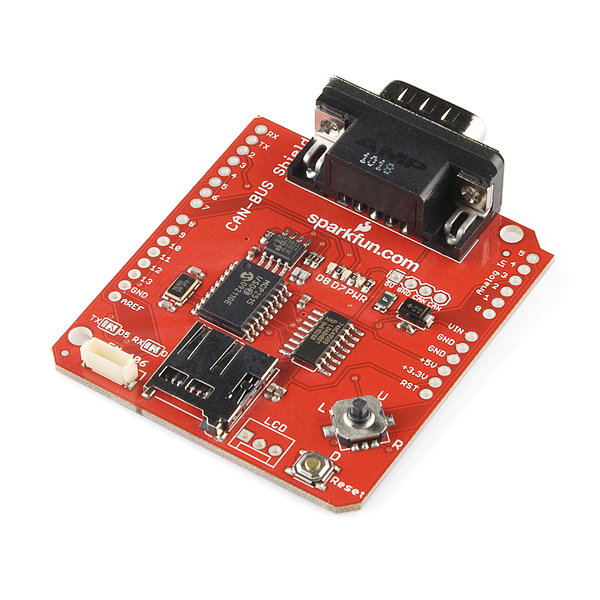
Pros: a feature-rich and well-made shield
Cons: not available locally, a special OBD-to-RS232 cable is required which is not easy to get
chipKIT Max32™ Prototyping Platform
The chipKIT™ Max32™ is based on the popular Arduino™ open source hardware prototyping platform but adds the performance of the Microchip PIC32 microcontroller. The Max32 is the same form factor as the Arduino Mega board and is compatible with many Arduino™ shields as well as larger shields for use with the Mega boards. It features a USB serial port interface for connection to the IDE and can be powered via USB or an external power supply.
The Microchip PIC32MX795F512 processor features:
- 80 Mhz 32-bit MIPS
- 512K Flash, 128K RAM
- USB 2.0 OTG controller
- 10/100 Ethernet MAC
- Dual CAN controllers

Pros: feature-rich (with CAN transeiver & USB host) , powerful processor, Ford’s OpenXC reference platform.
Cons: expensive, not available locally
DIY with MCP2551 and MCP2515
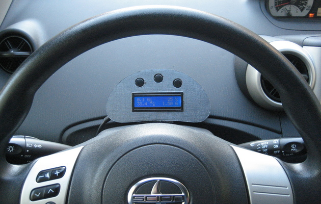
My inspiration for developing this gas gauge was after purchasing a new car (Scion Xa) and wondering what MPG I was getting. After much research on ODBII protocols (Scions support CAN-BUS), and looking into open source software that already existed (OBDuino32K) I delved into my first Arduino project.
This project has taken me over a year to put together from building my own CAN-BUS shield, learning to design a circuit board, soldering SMD parts and then building my own enclosure so I could mount it in my car.
Pros: cheap!
Cons: lots of work