This article will guide you through the simple steps to set up your own vehicle telemetry system with any computer (e.g. a PC) and some knowledge about Arduino.
Prerequisites
A vehicle tracking system allows one or more vehicles to be monitored in real-time from a user terminal (computer or mobile device).
Telemetry Data Server
Freematics Hub is a free light-weight telemetry data server which receives, caches, stores and illustrates data received from telemetry devices. Designed with efficiency and portability in priority, it runs on systems of any footprint, servers, desktops or a SBCs like Raspberry Pi. The computer running the software, however, must have inbound WAN access, in other word, an IP address accessible from Internet. This depends on broadband companies. If you deploy the server software on a virtual private server in the cloud, then this is not an issue. Two ports are used by Freematics Hub, 8080 for HTTP and 8081 for UDP. The ports must be unblocked for access.
Telemeter Device
In the context of vehicle telemetry, a telemeter device obtains vehicle data from engine, power train and various in-vehicle sensors as well as geo-location data from GSM base stations or GPS, and transmits the data to telemetry server in real-time.
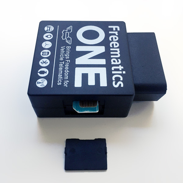
Freematics Vehicle Telemetry Starter Kit is a cost-effective Arduino compatible development kit designed for vehicle telemetry projects. As an Arduino programmable kit, it can work as, but not limited to, a vehicle telemeter device over GSM/GPRS network. The kit consists of:
- Freematics ONE (ATmega328p + 9-DOF motion sensor + OBD-II reader) or
- SIM800 or SIM5360 cellular module
- OBD-II extension cable
- microUSB cable
- GPS antenna (applicable to SIM5360 only)
- microSD card (optional)

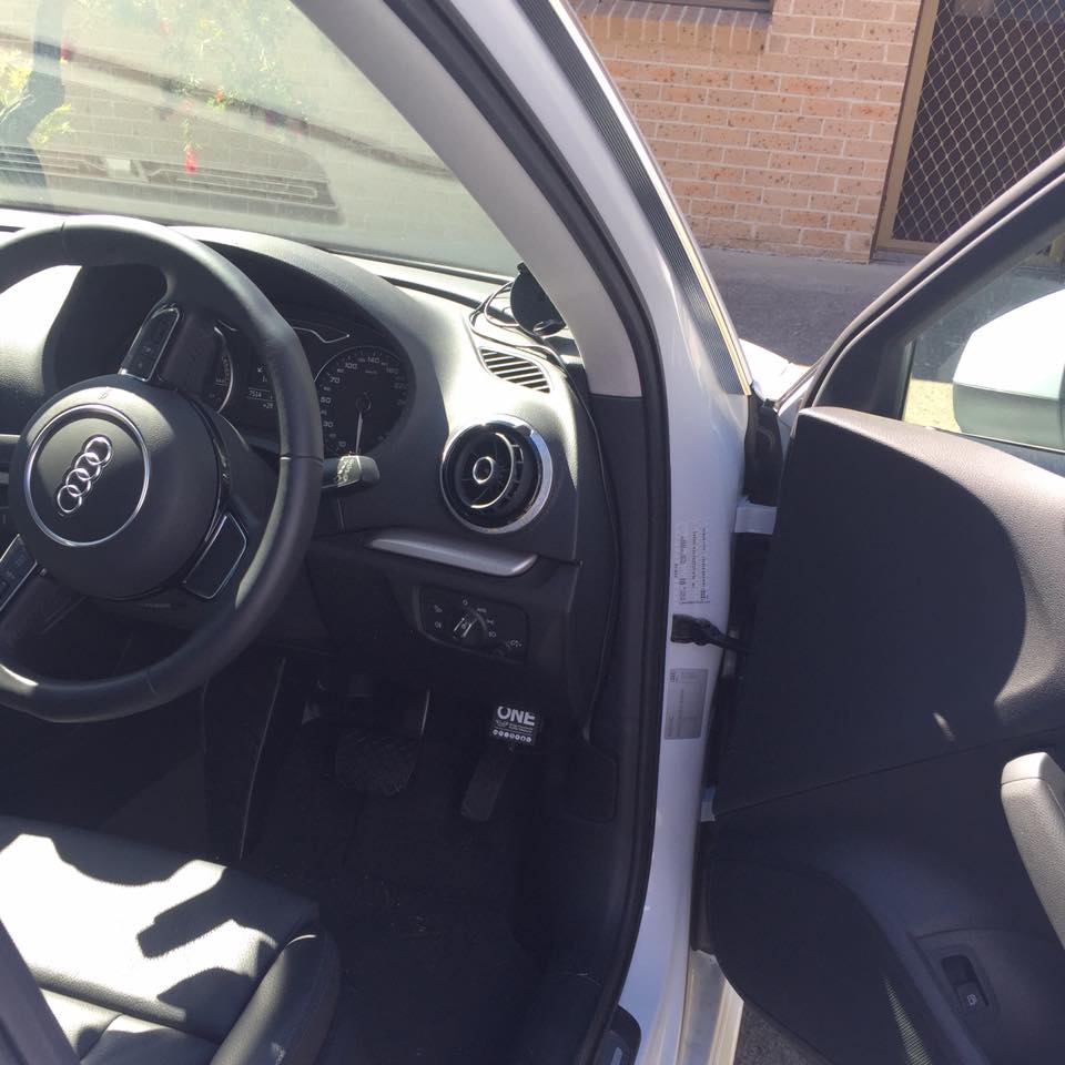 Freematics ONE plugs in the OBD port of a car, gets powered from there and work as it is programmed to do, which are normally reading out vehicle data, obtaining geo-location and measuring motion (like G-force and orientation) and uploading all the data to a remote server in real-time.
An actively maintained Arduino library is provided for easy programming with the kit. Fully functioning example sketches are available for various purposes as a quick start.
SIM card, data plan and APN
To use cellular network, SIM card is a necessity. Basically any micro SIM card with some usable data will work. A well designed transmission scheme for a vehicle telemetry system of average usage consumes lower than 50MB data monthly. If you could get a data SIM pooled with your mobile phone plan, the data cost would literally be nothing in addition.
It is important to obtain the correct APN of your mobile network operator. The APN could be different for prepaid or postpaid SIM even from the same operator. This information is normally available from operator company’s website.
Step by Step to Your Telemetry System
Now let’s start with the guide of setting up a complete vehicle telemetry system with Freematics Vehicle Telemetry Starter Kit and a common Internet connected PC.
Install Freematics Hub on your computer
Currently only Windows version of Freematics Hub is released. More distributions are coming soon. Meanwhile, let’s use a Windows PC.
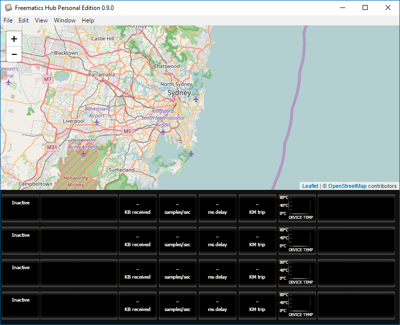
Download the installer from here and install it. The software has a console window displaying working status and a simple and clear GUI containing a map and a list for devices/cars you have.
Configure router for external access to the computer
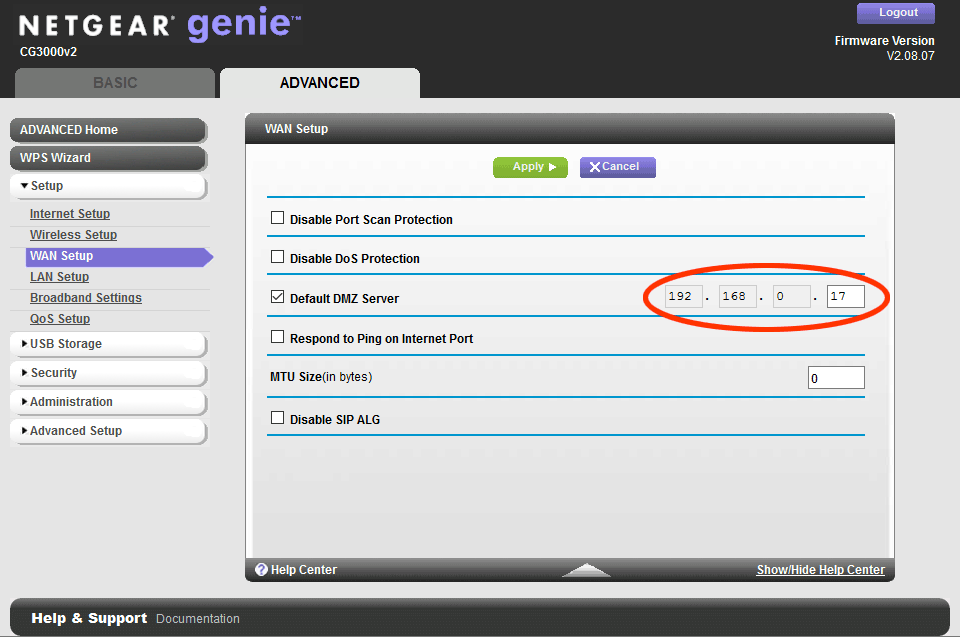
Login to the router admin page (normally 192.168.x.1) and set the DMZ server to the IP of the computer to be used as telemetry server. Alternatively, you can set port forwarding for port 8080 and 8081. This is pretty much same as setting up a web server or FTP server for external access.
Get the device ready
Now that you have Freematics Vehicle Telemetry Starter Kit, let’s get it ready for working as a vehicle tracker. Freematics ONE can connect to Internet by cellular module or WIFI module (through a hotspot like your mobile phone).
If you have Freematics ONE with cellular module kit your kit, put a SIM card into the card slot. To do this, remove the side cover, and insert the SIM card in the direction shown below (chip side facing up). Push it all the way till locked. To get it out, push the SIM card further a bit and it will be popped out.
Then, connect to Freematics ONE your computer by a supplied microUSB-to-USB cable. A serial port driver should be automatically installed. In case it is not, please download the driver and install it manually.
Compile and upload Arduino sketch
Freematics ONE is literally an Arduino UNO connected with some peripherals in the form of a OBD dongle. A sketch has to be uploaded to get it working. We provide fully functioning sketches for various purposes so you can get started easily. After playing well with it, you can evolve your own sketch with features you need.
Followings are the steps for compiling and uploading sketch to Freematics ONE.
1. Download and install Arduino IDE
Arduino IDE can be downloaded from Arduino website.
2. Import Arduino library for Freematics ONE
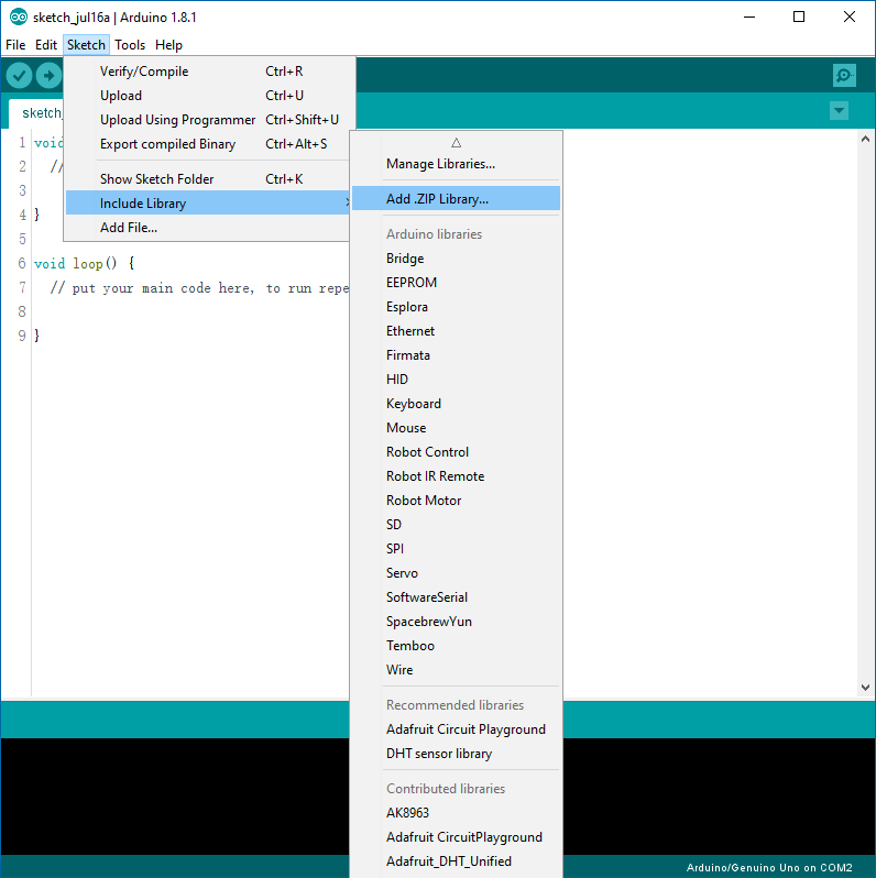
Download Freematics ONE Arduino library package. Launch Arduino IDE. Choose menu Sketch->Include Library->Add .ZIP Library and select the downloaded zip file. The library will be imported and new items will appear in the Examples menu.
3. Load the example sketch
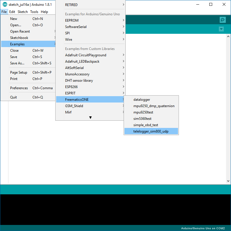
From the Examples menu, load example sketch telelogger_sim800_udp in the case of SIM800 module, or telelogger_esp8266 in the case of ESP8266 module.
Once the sketch is loaded, click on the tab and go to config.h. In the case of SIM800 module, change the APN setting and server address to your own one. The port setting is for the UDP port used on the server for receiving data and normally should be kept default. In the case of ESP8266 module, change WIFI SSID and password to the actual ones.
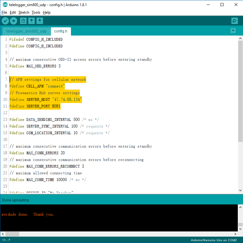
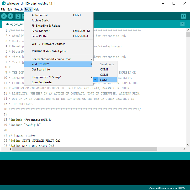
Once done, choose Arduino Uno as board and select the serial port of Freematics ONE, and click the Upload button to start compiling and uploading.
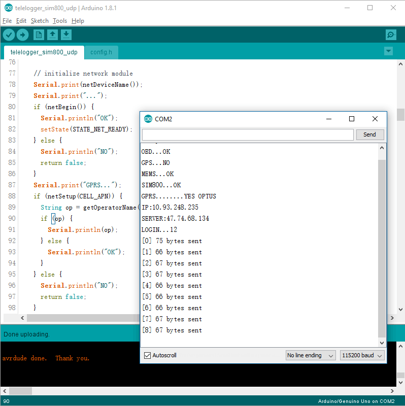
Once uploading successfully completed, we can connect Freematics ONE to car’s OBD port and see it running from serial monitor. Of course all above steps can be started with the device already plugged in OBD port. With everything good, the sketch runs like following.
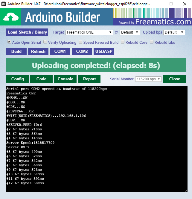
Alternatively, you can use Freematics Arduino Builder to compile and upload code. When you don’t need to modify the code, this tool provides an efficient process to get the code running on the device and monitor the serial output on the spot.
Watch the data coming in
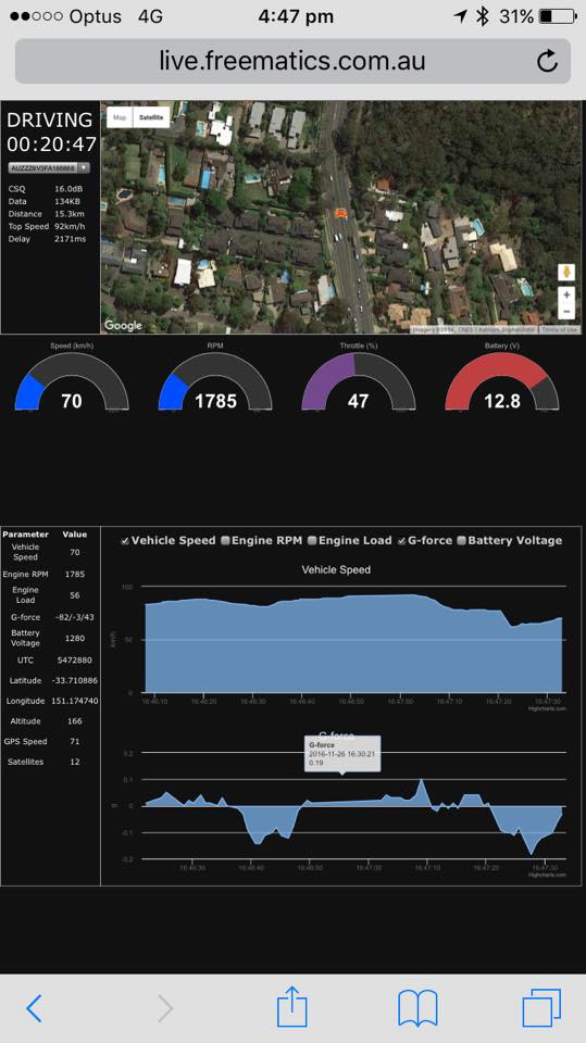
At this time, real-time data is being transmitted from your car to your data server. Freematics Hub GUI will immediately start to update with data received.
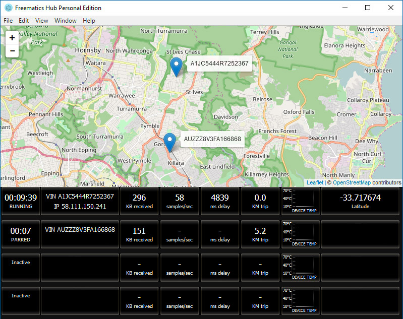
To quickly go through real-time data, click on the right-most block of list entry. To view data grid and charts of a specific vehicle, click on VIN/IP block.
The GUI can be viewed from a mobile device remotely. Simply open web browser on mobile device and pop in your server address.