This will be the most comprehensive OBD-II data logger kit and also the biggest in size as it is based on Arduino MEGA2560. Te kit consists of:
- Arduino MEGA2560
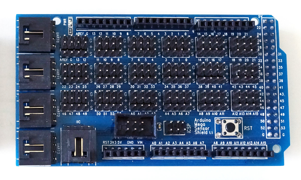
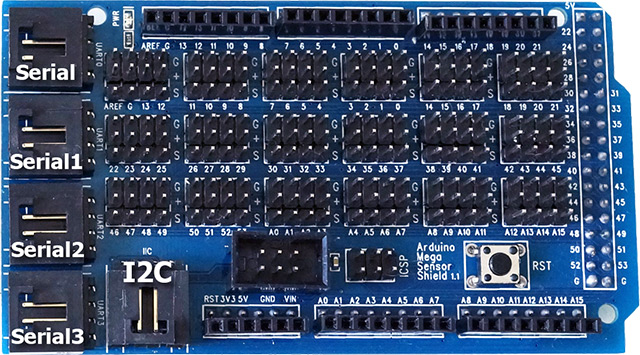
- Arduino MEGA I/O extension shield
- Arduino OBD-II Adapter Model B
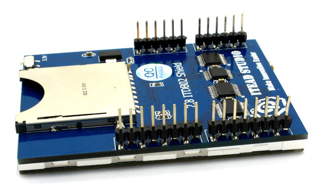
- 2.8″ TFT LCD shield for Arduino (with SD socket)
- UART GPS Receiver (5Hz or 10Hz)
With this kit, following data can be displayed and recorded to SD card.
- OBD-II data (all PIDs available in vehicle)
- GPS data (5Hz/10Hz update rate)
- 3-axis accelerometer data
- 3-axis gyro data
- temperature sensor data
Gallery
-
- Arduino MEGA I/O expansion shield
-
- LCD TFT shield for Arduino (back)
Wiring
With the MEGA I/O shield, it is very handy to connect everything. The connector from the OBD-II adapter should be plugged into the I2C socket on the I/O shield. The 4-pin connector from GPS receiver should be plugged into I/O shield’s UART2 socket.
OBD-II adapter line definition:
- Red: VCC (5V)
- Black: GND
- Blue: SDA (or D20)
- Yellow: SCL (or D21)
GPS line definition:
- Red: VCC
- Black: GND
- Green: Tx (to Arduino Serial2 Rx or D17)
- White: Rx (to Arduino Serial2 Tx or D16)
MEGA Logger
The MEGA Logger is a complete sketch developed for the kit working as a OBD-II and GPS data logger with live data display. The source code is available here. For getting started easier, a complete package containing the sketch and all referenced libraries is available here.
After being able to record all the data, it is then possible create a KML with Data2KML utility and display the data with Google Earth like this:

FAQ
Q: How to make the SD card socket on the TFT LCD shield work with Arduino MEGA 2560?
A: Go to <Arduino Dir>/libraries/SD/utility, open Sd2Card.h file, find and uncomment following line:
#define MEGA_SOFT_SPI 1
Open config.h file in sketch directory, uncomment this line:
#define SD_CS_PIN 10
And comment out this line:
#define SD_CS_PIN SS