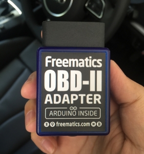
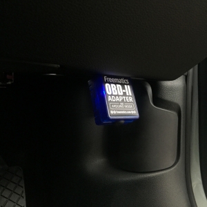
Freematics Vehicle Data Logger is a programmable device with OBD-II and GPS accessibility. Inside it is an AVR ATMega328P (compatible with Arduino UNO) and peripherals accessible with Arduino libraries including voltmeter, accelerometer, gyroscope, temperature sensor, microSD seat and Bluetooth (BLE and SPP) module.
Porgramming the Hardware
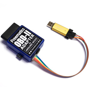
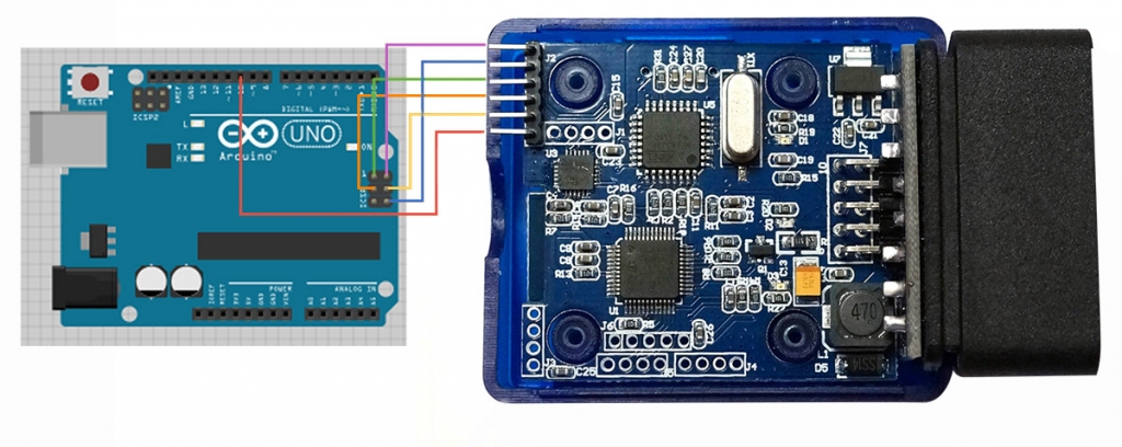
The onboard ATMega328P is programmed via ICSP, either by USBasp or Arduino as ISP. Both ways are supported by Arduino IDE.
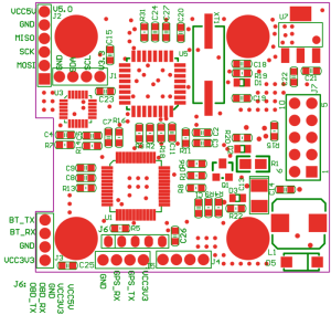
The ICSP pins (also for SPI communication or using as GPIO) are located at one corner of the PCB and is accessible from outside the enclosure.
Programming with USBasp
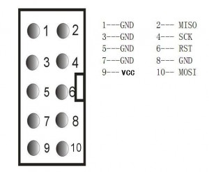
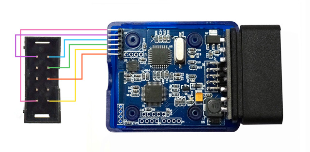
A USBasp programmer has 6 useful pins. To program with USBasp , connect the adapter’s SPI pins with USBasp’s pins as following:
MISO 2-MISO
SCK 4-SCK
RESET 6-RST
GND 8-GND
VCC 5V 9-VCC (*)
MOSI 10-MOSI
Programming with Arduino as ISP
An common Arduino board can work as ISP for another Arduino board with Arduin ISP sketch loaded. To program with Arduino, connect the adapter’s SPI pins to Arduino’s ICSP pins and the reset pin to Arduino’s D10.
Required Software
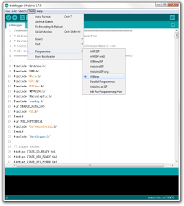
Arduino IDE is the recommended development environment for Freematics Vehicle Data Logger. Set board to Arduino UNO and everything is same as if programming an Arduino UNO. Arduino Builder is an alternative tool for quickly compiling and uploading sketch to the device via programmer.
Sketches (aka firmware)
Freematics Vehicle Data Logger contains Arduino UNO compatible main controller. So you can think it as an Arduino which requires a sketch to be uploaded to work. You can develop your own sketch for it as you do with Arduino. To help users get started easily and more rapidly, we have developed a ready-to-go Arduino sketch.
With Data Logger Sketch loaded, Freematics Vehicle Data Logger will work as a comprehensive vehicle data logger which logs OBD-II, GPS and motion sensor data onto the inserted microSD card whenever the car engine is running. With embedded Bluetoothmodule, data can also be streamed data to mobile device (e.g. smartphone or tablet).
The sketch references following custom Arduino libraries:
The sketch has several configurable options all staying in the config.h file. Major options include:
- USE_GPS – defines whether GPS is used
- USE_MPU6050 – defines whether MPU6050 (accelerometer & gyro) is used
- USE_MPU9150 – defines whether MPU9150(accelerometer, gyro, compass) is used
- ENABLE_DATA_LOG – toggles data logging on microSD card
- ENABLE_DATA_OUT – toggles data streaming (to mobile devices via Bluetooth)
- STREAM_FORMAT – sets streaming data format (binary or text)
- LOG_GPS_NMEA_DATA – logs raw GPS NMEA data
- LOG_GPS_PARSED_DATA – logs parsed GPS data
By default, data is logged in a simple CSV text format.Each line represents a record with time, data type and data value like this:
[Time Elapsed],[Data Type],[Data Value]
Time Elapsed is the time elapsed in milliseconds since previous data record. Data Type is the OBD-II PID which is defined in the OBD-II library (e.g. 0x10C is engine RPM). Here is an example data clip:
169,10D,0
171,111,12
170,143,21
165,10B,30
175,10C,705
169,10D,0
170,111,12
…
GPS and motion sensor data are defined as special PID which OBD-II standard does not use and are defined in datalogger.h file.
#define PID_GPS_LATITUDE 0xA
#define PID_GPS_LONGITUDE 0xB
#define PID_GPS_ALTITUDE 0xC
#define PID_GPS_SPEED 0xD
#define PID_GPS_HEADING 0xE
#define PID_GPS_SAT_COUNT 0xF
#define PID_GPS_TIME 0×10
#define PID_GPS_DATE 0×11
#define PID_ACC 0×20
#define PID_GYRO 0×21
Getting Started Step by Step
1. Wire the device with programmer (USBasp or Arduino as ISP) as is decribed in the Programming the Hardware section
2. Connect the programmer to computer’s USB port.
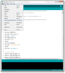
3. Start Arduino IDE, load the datalogger sketch (install all the libraries if not done) and choose USBasp or Arduino as ISP to upload the sketch.
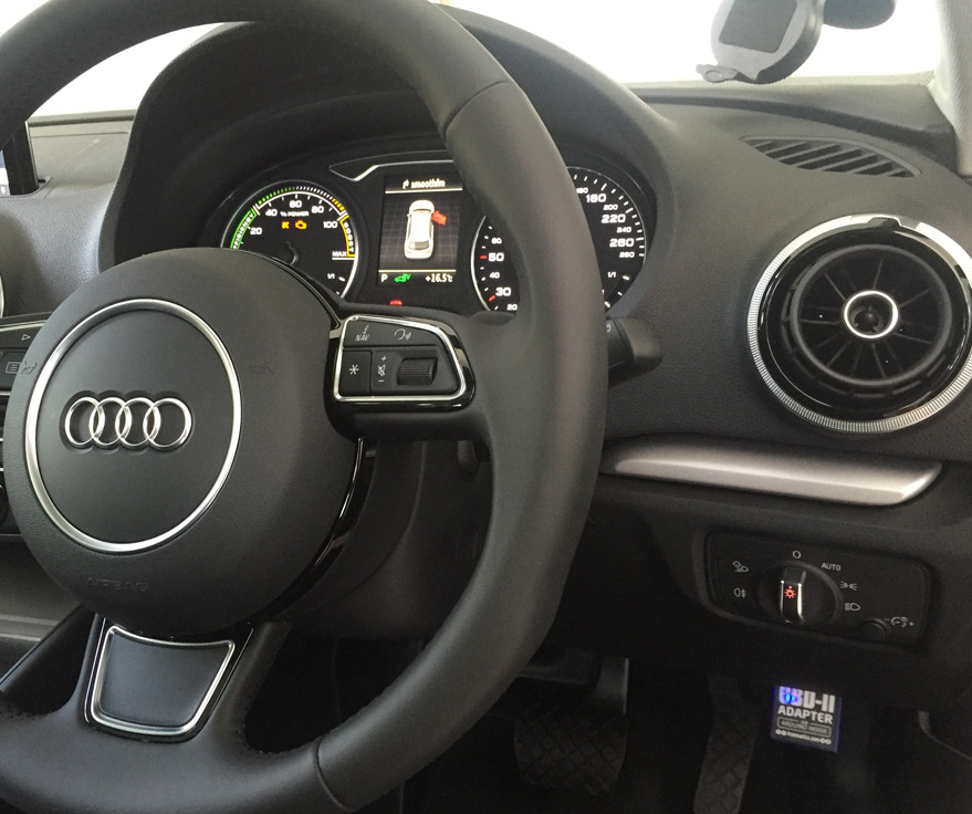
4. Unplug the device from programmer, insert a microSD card (if you need data logging) and go to your car, locate your OBD-II port and plug in the device into the port.
Turn on the car’s ignition key (not necessarily starting the engine) and the LED in the device enclosure should start flashing. If a microSD card is inserted, it will start logging data onto the the card. By default each file is limited to 256KB in size and a new file will created once the size is reached. You can change the option in config.h.
As is implemented in the sketch, if the device is powered on without pluggin into OBD-II port, it will start working in GPS & MEMS logging mode. Within a defined preiod of time (30 seconds), it will attempt to connect to OBD-II and give up that afterwards. Of course you can change this too.
5. If Bluetooth is in your configuration, you can view the live data from your smartphone or tablet
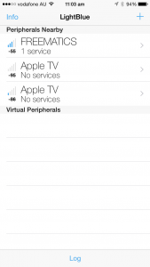
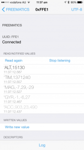
On iOS, install LightBlue Explorer from App Store. Once opened, it will show the nearby BLE devices. Choose Freematics (sometimes shown as HMSoft) and go with prompt. Tap on the top right option to change the data format to UTF-8 (default is HEX) and tap on Listen for notifications and you will see data coming and updating like following.
Now that data is available to your smartphone, you can start writing your own App to do something with the data.
6. How to view logged data?
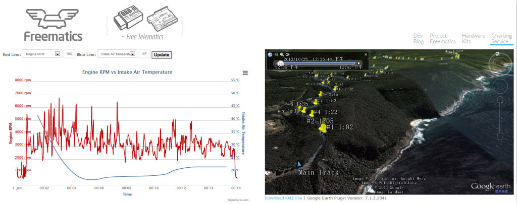
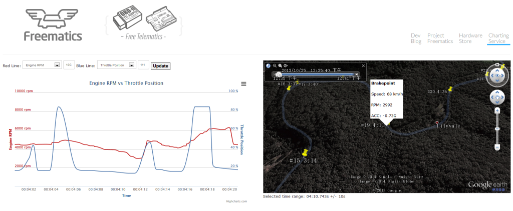
The easiest way is using Freematics Data Charting Service, an online service which renders data log file into interactive chart and map in your web browser.
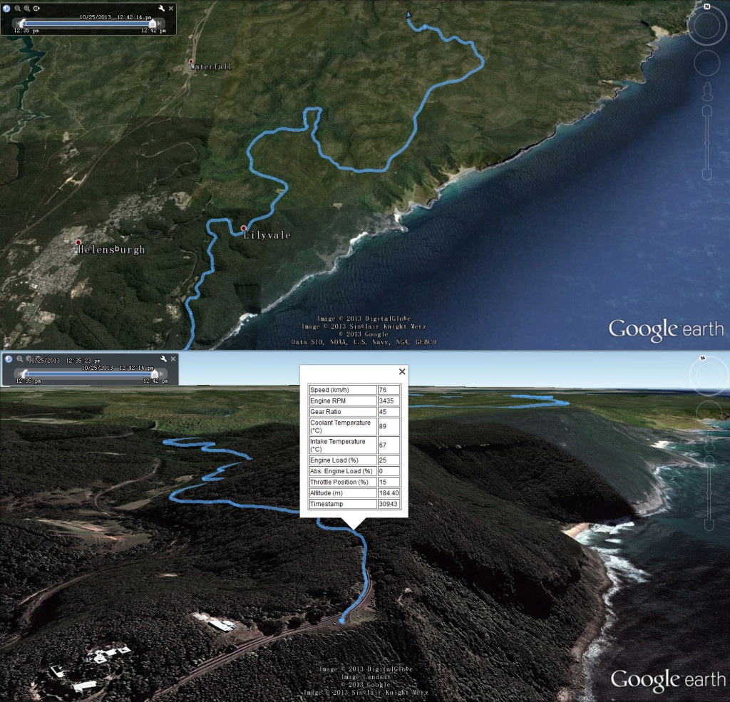
If you prefer to do everything offline, Data2KML is provided as an open-source utility for converting data log file to KML format which can be loaded by Google Earth.


